In brief
A dehumidifier’s pump-lift specification and the length of its drain hose answer different questions. Record the rise in the route, the full tubing path, and the manufacturer’s restrictions separately. A destination that appears close enough on the floor plan may still need a route the appliance does not support.
Three measurements to keep separate
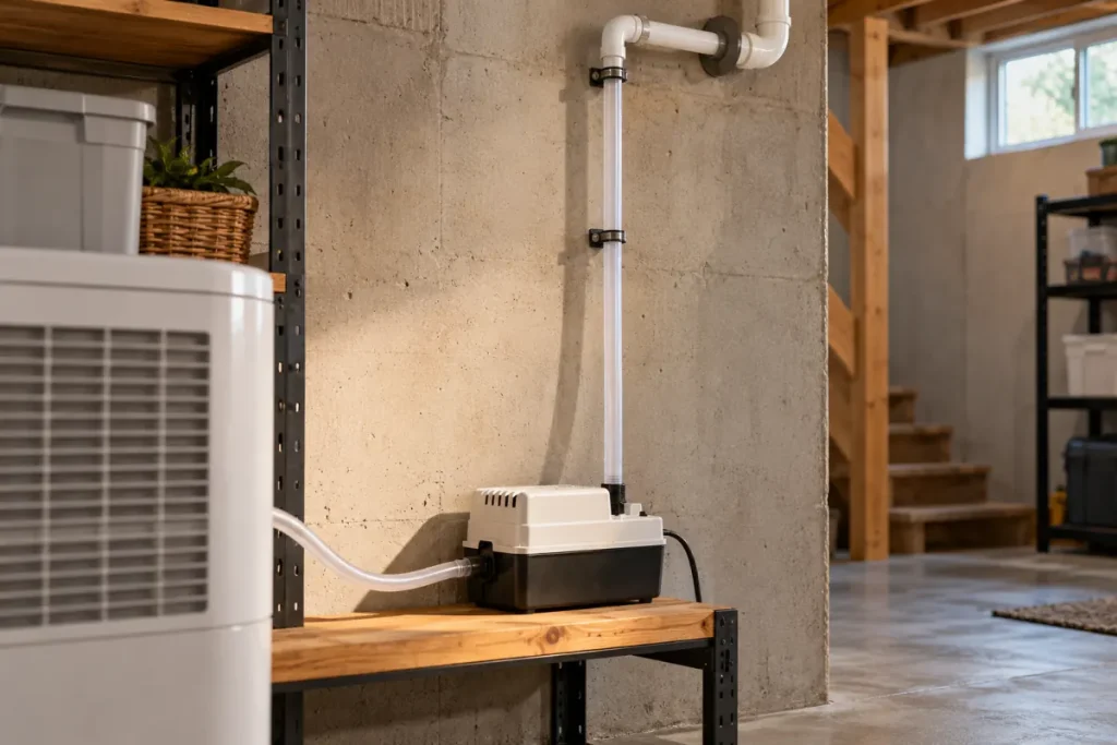
Vertical rise describes how far the water must move upward. Route length describes the full tubing path, including horizontal sections and turns. Hose requirements specify the tubing and connections that the manufacturer permits. A measurement for one of these does not establish compatibility with the others.
GE’s drainage overview, for the equipment it describes, gives a vertical pumping limit and also says not to extend the supplied tubing. Treat them as separate restrictions. This is a manufacturer example, not a universal pump specification.
Read the exact manual before planning a route
Find the model number on the appliance or proposed purchase. Locate its pump section, installation diagrams, hose instructions, and operating conditions. Save the manual reference and page numbers in your plan. Product titles and comparison cards may leave out conditions that matter.
For a concrete example, the GE manual 49-5000545 Rev. 4, linked from the APHL50LB owner page, lists a 16-foot maximum lift in its pump section. That figure belongs to the covered equipment and that manual. It is not evidence that another model, a longer hose, or every route under 16 feet will work.
Use the official model support page to see the manual’s provenance. This reference is an example of reading a specification; we have not tested or recommended that product.
Sketch the whole route
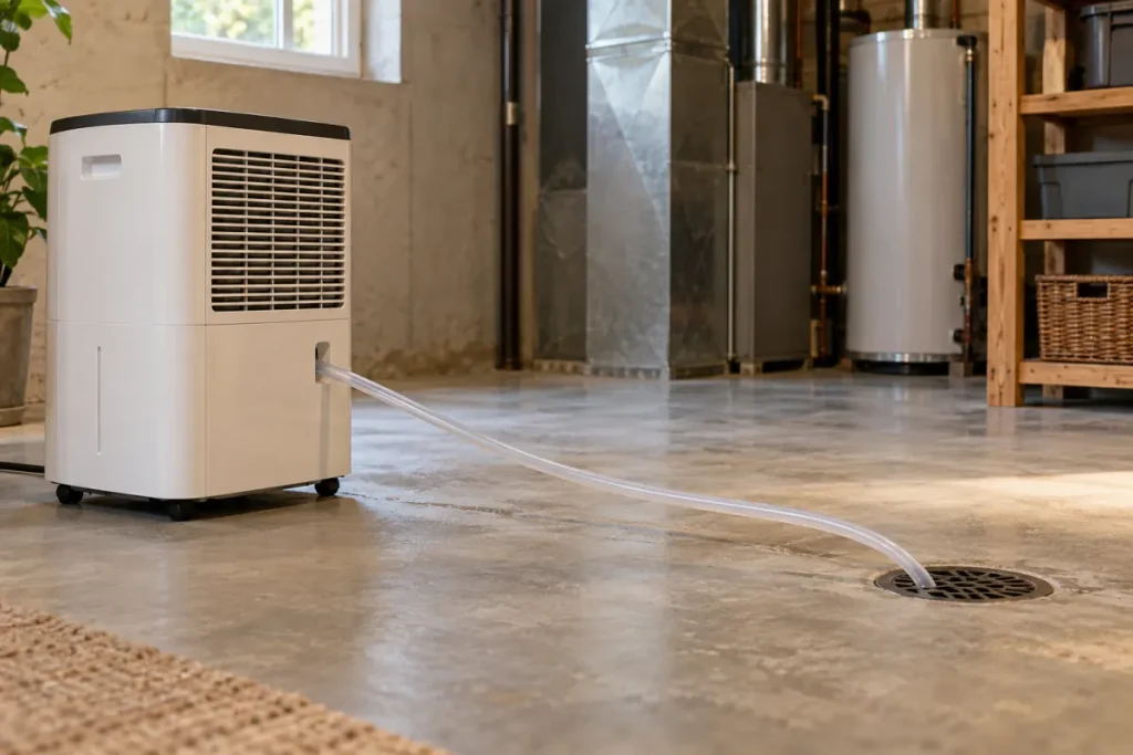
Mark the appliance outlet, each upward section, the highest point, and the intended destination. Record the complete path rather than the straight-line distance between appliance and drain. If the manual is unclear about the reference point for lift or a route with several rises, ask the manufacturer to assess your sketch.
Illustration only: imagine a route that rises 6 feet and then runs 8 feet horizontally before reaching its destination. That description gives a 6-foot rise and at least 14 feet of tubing path before adding bends or other sections. It does not prove the route is supported. Compare both quantities with the exact instructions; do not subtract horizontal length from an advertised lift figure.
Keep unresolved requirements visible
| Requirement | What to record | When to ask for clarification |
|---|---|---|
| Lift definition | Manual wording and measurement reference point | The diagram does not explain your route |
| Total tubing path | Every section and permitted hose length | The route needs extra tubing or a connector |
| Hose and fittings | Supplied or explicitly supported parts | A seller proposes a substitute |
| Discharge destination | Location and confirmation it is suitable | Building or drainage requirements are uncertain |
Our blank pump-route and support worksheet keeps these questions together. It performs no pump sizing or compatibility calculation. A “not confirmed” entry is useful information to resolve before purchasing fittings or running the arrangement.
Observe the supported setup after installation
Follow the owner instructions for connections, activation, and checks. Use our pump-start observation guide to record what the controls and drainage actually do. Keep the setup under observation during the first permitted cycle; a plan alone is not proof that the hose is secure or water reaches the intended destination.
If a safe, supported downhill destination exists, review the bucket, gravity, and pump comparison. The useful choice is the method that fits the room, the exact equipment, and a suitable destination—not a pump chosen just because the feature appears on the box.